2D Active Nematic Liquid Crystal
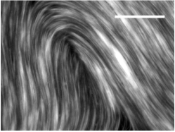
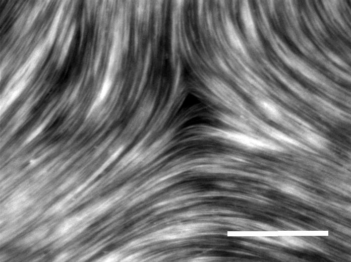
We form an active nematic by concentrating microtubules and kinesin motor clusters onto a flat, 2D oil-water interface. Once depleted into confinement, the quasi-2D film of microtubule bundles align forming a nematic. The Kinesin motors exert inter-filament sliding forces which result in an extensile active nematic.
Active Nematic Experiments |
Isotropic vs Nematic |

We deplete the active microtubule bundles to a surfactant stabilized oil-water interface, The bundles spontaneously form an active nematic.
|
A liquid crystal is a phase of matter that exists between the liquid phase and the crystalline phase. It is a material which retrains some fluid properties yet is not completely isotropic as one would expect in a fluid. A nematic is an example of a liquid crystal in which the constituent particles have a preference to align with one another along one orientation in the system.
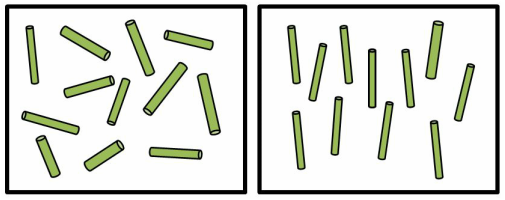
In an isotropic system, particles are equally likely to point in every direction. In a nematic, the particles have orientational order, and prefer to point in one direction.
|
Motile Defects in the Active Nematic
|
The active stresses generated by the kinesin motors result in regions of the nematic which bend and distort. In some regions, the bend becomes very large and dislocations in the system are created. These are called defects. They are regions in which the orientation of the microtubules is undefined. The defects that appear in the video below are called +1/2 and -1/2 defects and the number 1/2 comes from the winding of the orientation of the microtubules around the core of the defect and the sign from the direction of the rotation.
|
Nematic Defects
|
Defect Orientation Order
|
To quantify defect dynamics in this system, Gabriel S. Redner from Michael Hagan's group at Brandeis University, developed a defect tracking algorithm which finds defects and their orientations. Defect positions are shown in the video to the right as yellow dots. Their orientation (direction they are pointing) is shown as a red line.
|
|
|
Surprisingly, the +1/2 defects in our active nematics obtain orientation order over the entire sample lifetime (hours) and the order spans the entire sample area (few centimeters). The defects have nematic symmetry which persists in time and space.
|
|
For more information on orientational order in active nematics, check out the following publication:
Orientational order of motile defects in active nematics
S. J. DeCamp*, G. S. Redner*, A. Baskaran, M. F. Hagan, Z. Dogic.
Nature Materials, Aug 2015; 14, 1110-1115.
(News and Views by: Denis Bartolo)
Orientational order of motile defects in active nematics
S. J. DeCamp*, G. S. Redner*, A. Baskaran, M. F. Hagan, Z. Dogic.
Nature Materials, Aug 2015; 14, 1110-1115.
(News and Views by: Denis Bartolo)